This is a guide to combining Autodesk Revit content with Cesium ion datasets within NVIDIA Omniverse, using the Autodesk Revit connector and the Cesium for Omniverse extension.
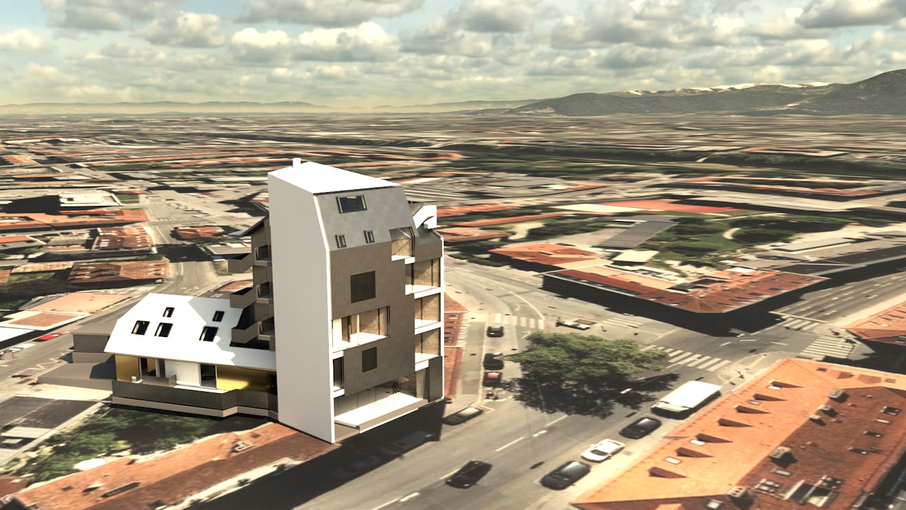
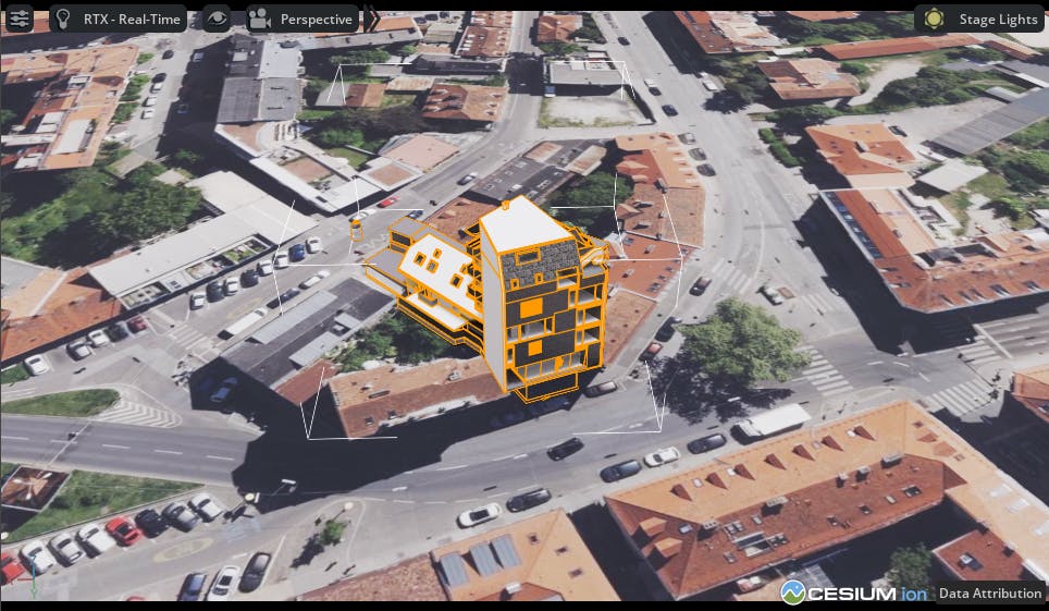
Architectural model exported from Autodesk Revit and georeferenced onto Cesium World Terrain with Bing Maps Aerial imagery.
You’ll learn how to:
- Prepare and export 3D content from Autodesk Revit.
- Accurately position this content on Cesium World Terrain.
- Know how to set up a basic Cesium for Omniverse stage in NVIDIA Omniverse USD Composer. Check out our Cesium for Omniverse Quickstart guide for instructions on starting with the Cesium for Omniverse extension.
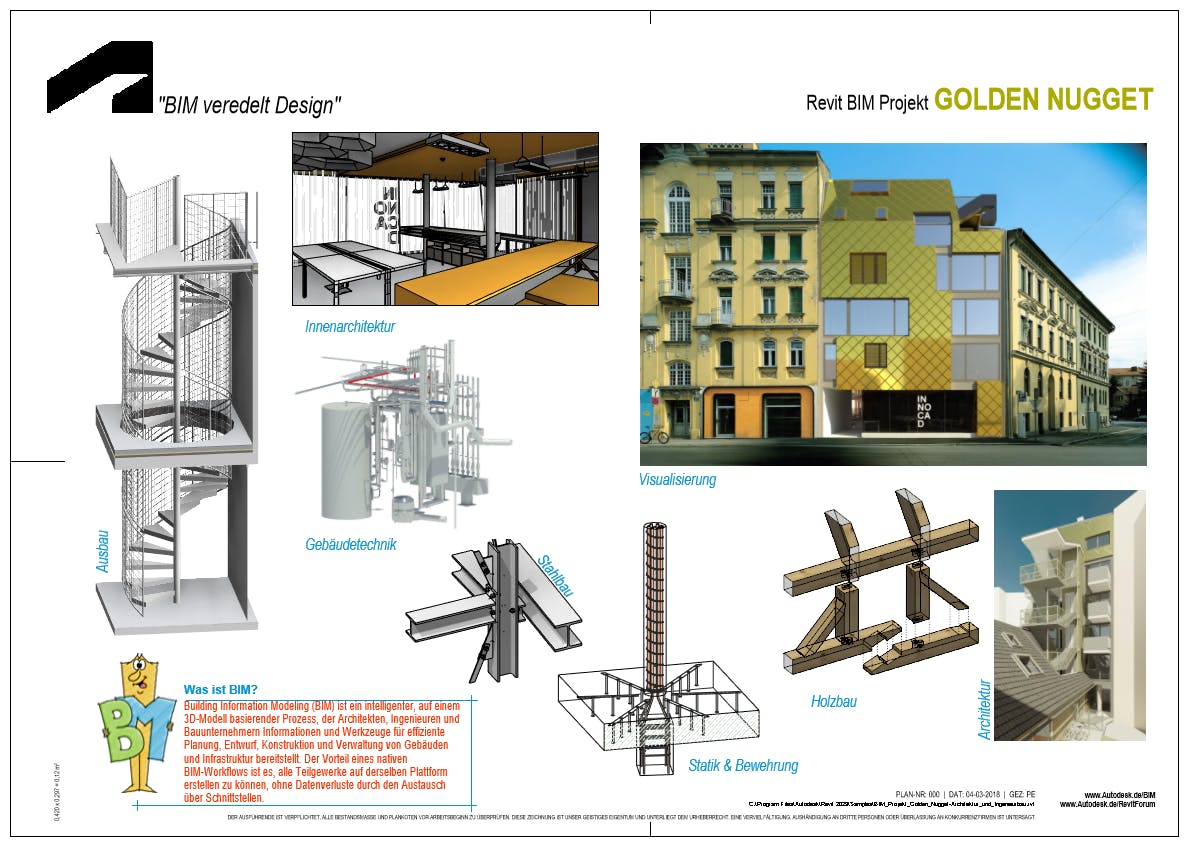
- The Autodesk Revit “Golden Nugget” sample scene shipped with Autodesk Revit 2023. This is typically found at the following location:
C:\Program Files\Autodesk\Revit 2023\Samples\BIM_Projekt_Golden_Nugget-Architektur_und_Ingenieurbau.rvt - The Autodesk Revit Omniverse connector Beta 202.0.2400 installed from the Omniverse Launcher.
3D design software commonly favors local Cartesian coordinate systems over geographic ones to meet the demands of precision, accuracy, and simplified workflows. Local coordinate systems offer a convenient method for defining and manipulating precise measurements without the complications associated with geographic factors like Earth's curvature and latitude-longitude coordinates.
When it comes to Cesium for Omniverse, it typically adopts a geographic, Earth-centered Earth-fixed coordinate system, representing Earth as an accurate 3D globe. Consequently, to position an architectural model represented in local coordinates onto a geographic dataset such as a globe, a coordinate conversion process becomes necessary.
This tutorial demonstrates a workflow for aligning an Autodesk Revit architectural model with Cesium World Terrain. It is important to note that while the workflow in this tutorial can accurately position Revit data on the globe, it does not feature a way to account for the curvature of Earth. This means for particularly large scenes, data at the edges of the model may not be accurately positioned with respect to the surface of the Cesium globe. Most architectural projects created with Revit are small enough in geographic size for this to not be noticeable.
1Open the Golden Nugget sample scene in Revit.
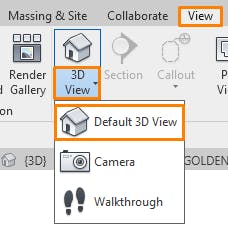
2Click View > 3D View > Default 3D View to enter the 3D view.
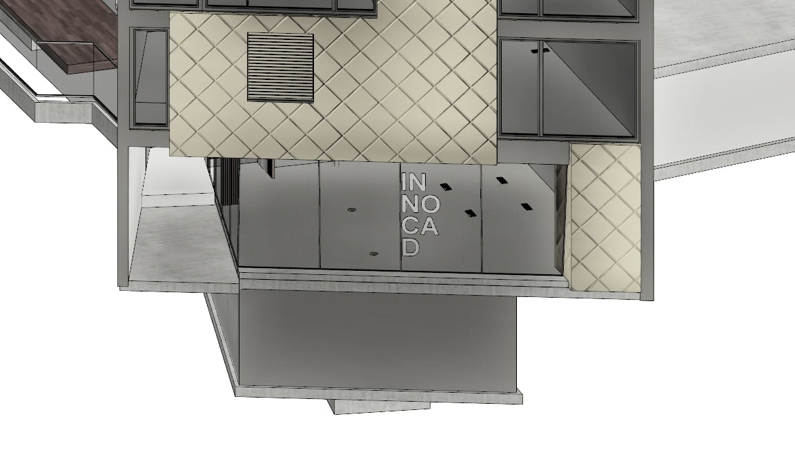
3Scroll to zoom in closer to the ground floor facade of the building.
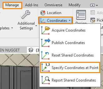
4This model does not have an accurate survey point configured. One can be made by clicking Manage > Coordinates > Specify Coordinates at Point.
The survey point is used to align a Revit model with a real-world location in a grid coordinate system. This information is used to accurately obtain latitude and longitude information for a specific location within your model. Established Revit files may already have a survey point configured that can be used without needing to manually specify coordinates. To accurately georeference these files with Cesium for Omniverse, you need to know the EPSG code of the projected coordinate system in use.
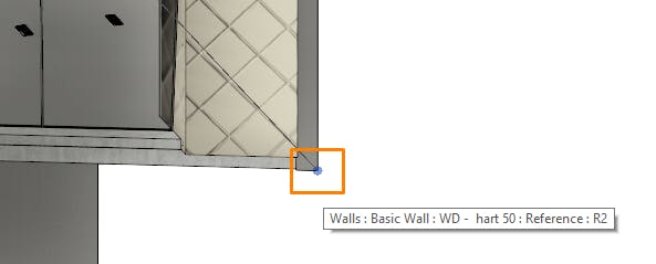
5Hover over the outer lower corner of the wall, and left click to place a survey point at this location.
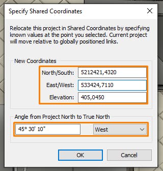
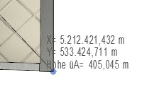
6A dialog will appear, prompting you to enter the real-world coordinates for this location. For this particular model, we will use the following real-world UTM coordinates located in Zone 33 (EPSG 32633):
- North/South: 5212421.432 m
- East/West: 533424.711 m
- Elevation: 405.045 m
- Angle from Project North to True North: 45° 30' 10" West
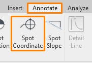
7Confirm the survey point is configured correctly by clicking on Annotate > Spot Coordinate.
8Hover over the location that the survey point was configured on, and confirm the coordinates match those entered above. If the coordinates are different, repeat the steps above to set up the survey point and confirm you have entered the correct values. Press ESC to cancel the Spot Coordinate tool.
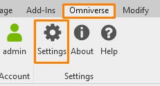
9Click on Omniverse > Settings to open the Settings dialog.
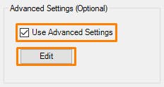
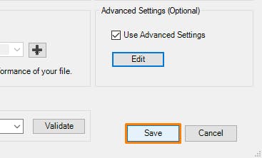
10Tick Use Advanced Settings; then click Edit.
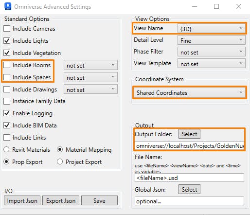
11Be sure the following settings are configured correctly:
- Ensure Include Rooms and Include Spaces are unticked.
- For View Name, choose the {3D} view created earlier in this tutorial.
- Under Coordinate System, be sure to choose Shared Coordinates. This will ensure the Revit file is exported at its correct real-world location.
- Select an Output Folder to export your USD to.
12Click Save to close the Advanced Settings dialog.
13Click Save to close the Omniverse Settings dialog.
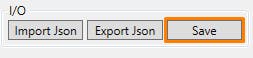
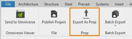
14Export the scene by clicking Omniverse > Export As Prop. This will begin the export process to USD.
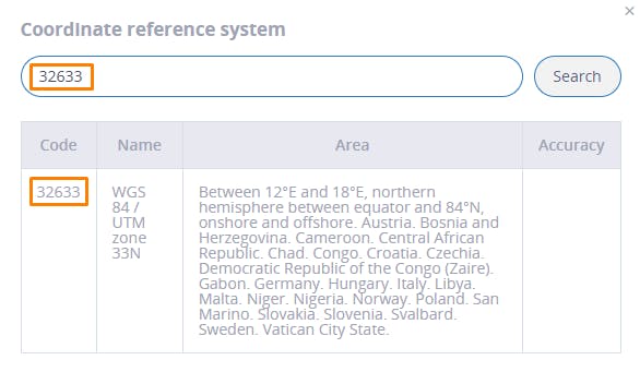
1Visit the epsg.io coordinate calculator in your browser.
2Under Input coordinate system, click Change.
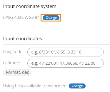
3Search for the EPSG code that represents the coordinate system for your project and select it. For this tutorial, our project data is projected in EPSG:32633.
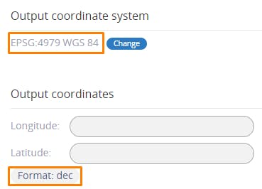
4Under Output coordinate system, ensure that EPSG:4979 WGS 84 is selected and that the format under Output coordinates is set to dec.
5Under Input coordinates, enter the EPSG:32633 location that corresponds to the survey point in the Revit scene. For our project this is X: 533424.711 and Y: 5212421.432.
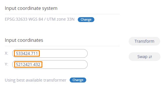
6Click the Transform button to convert the coordinates.
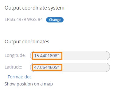
7The resulting latitude and longitude should be displayed under Output coordinates. Write these values down, as they will be used in the next step. You can also click Show position on a map to confirm the provided coordinates align with the correct location on Earth for your project.
1Open Omniverse USD Composer, ensuring the Omniverse Fabric Scene Delegate is enabled as per the quickstart tutorial.
2Click Edit > Preferences to open the Preferences window.
3Click Stage, then set Z as the Default Up Axis. This will ensure our stage follows the up-axis convention of typical AECO tools, making it easier to find and adjust coordinates.

4Click File > New to create a new empty scene. Remove the default ground surface.
5Click File > Add Payload, and select the USD file created during Step 1.
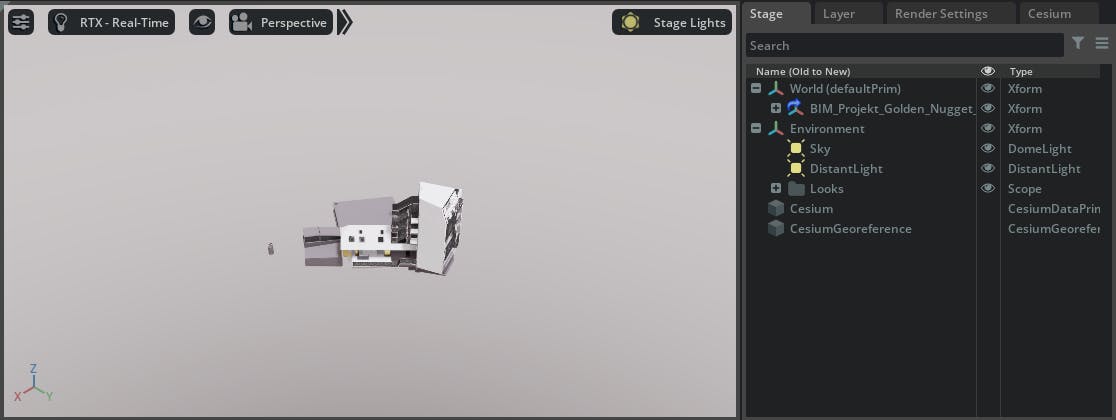
6Your Revit content should now be loaded in the stage. However, it will not be visible as the Revit connector exports it at its accurate, shared coordinates location. In this case, it is located at its real-world UTM easting and northing. Press F to zoom extents.
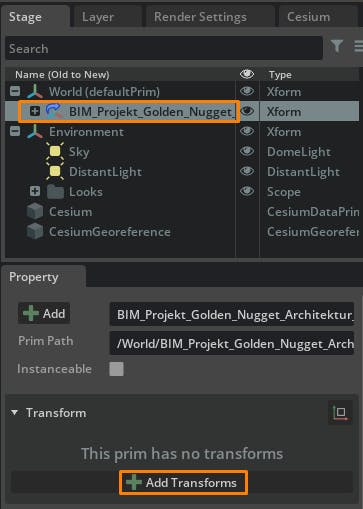
7Select the payload in the stage, and click Add Transforms in the Transform section of the Property window.
8The payload needs to be shifted to 0,0,0, so that we can align it correctly with Cesium World Terrain. To do this, we’ll offset the X and Y values by the original easting and northing of our survey point, converted to centimeters (Omniverse default units). This will move the Revit model to 0,0,0, ensuring the location of the survey point is exactly located at 0,0,0 in the stage. Enter the following values to do this:
- X: -53342471.1
- Y: -521242143.2

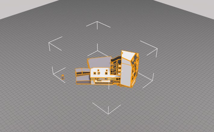
9Press F to zoom extents to the payload. You should notice it is now hovering above the origin of the stage, as indicated by the grid.
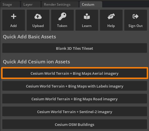
10From the Cesium window, add Cesium World Terrain + Bing Maps Aerial imagery to the stage.
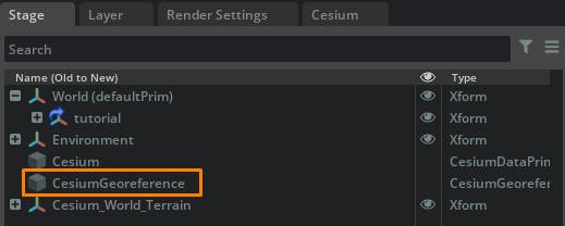
11From the stage, select the CesiumGeoreference prim to display its properties in the Property window.
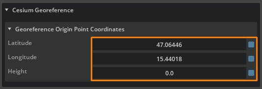
12In the Property window, enter the latitude and longitude obtained from EPSG.io. Enter the height value as 0.0, as our survey point represents an accurate height value with respect to Cesium World Terrain.
13The design should now match accurately with Cesium World Terrain.
Follow our Lighting the Stage and Capturing Images and Video tutorials to prepare your project and capture amazing visuals.