Cesium for Omniverse: Autodesk 3ds Max
This is a guide to combining Autodesk 3ds Max content with Cesium ion datasets within NVIDIA Omniverse, using the Autodesk 3ds Max connector and the Cesium for Omniverse extension.
You’ll learn how to:
- Prepare and export 3D content from Autodesk 3ds Max.
- Accurately position this content on Cesium World Terrain.
- Know how to set up a basic Cesium for Omniverse stage in NVIDIA Omniverse USD Composer. Check out our Cesium for Omniverse Quickstart guide for instructions on starting with the Cesium for Omniverse extension.
- An Autodesk 3ds Max scene representing a real-world location, georeferenced to a UTM or similar projected coordinate system with a valid EPSG code. A sample scene to use for this tutorial can be downloaded here.
- The Autodesk 3ds Max Omniverse connector installed from the Omniverse Launcher.
3D design software commonly favors local Cartesian coordinate systems over geographic ones to meet the demands of precision, accuracy, and simplified workflows. Local coordinate systems offer a convenient method for defining and manipulating precise measurements without the complications associated with geographic factors like Earth's curvature and latitude-longitude coordinates.
When it comes to Cesium for Omniverse, it typically adopts a geographic, Earth-centered Earth-fixed coordinate system, representing Earth as an accurate 3D globe. Consequently, to position an architectural model represented in local coordinates onto a geographic dataset such as a globe, a coordinate conversion process becomes necessary.
This tutorial demonstrates a workflow for aligning a 3ds Max road design model, created in a projected coordinate system based on the project's original plans. It is important to note that while the workflow in this tutorial can accurately position 3ds Max data on the globe, it does not feature a way to account for the curvature of Earth. This means for particularly large scenes, data at the edges of the model may not be accurately positioned with respect to the surface of the Cesium globe.
Depending on your use case, this may not be an issue. A common workflow is to use a geospatial dataset such as the Cesium globe as “background” content, where its primary function is to provide visual context only and lower levels of accuracy are acceptable. Ultimately, your use case will determine the levels of accuracy required in your design and context data.
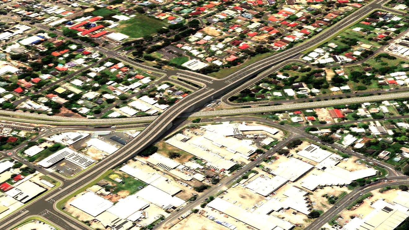
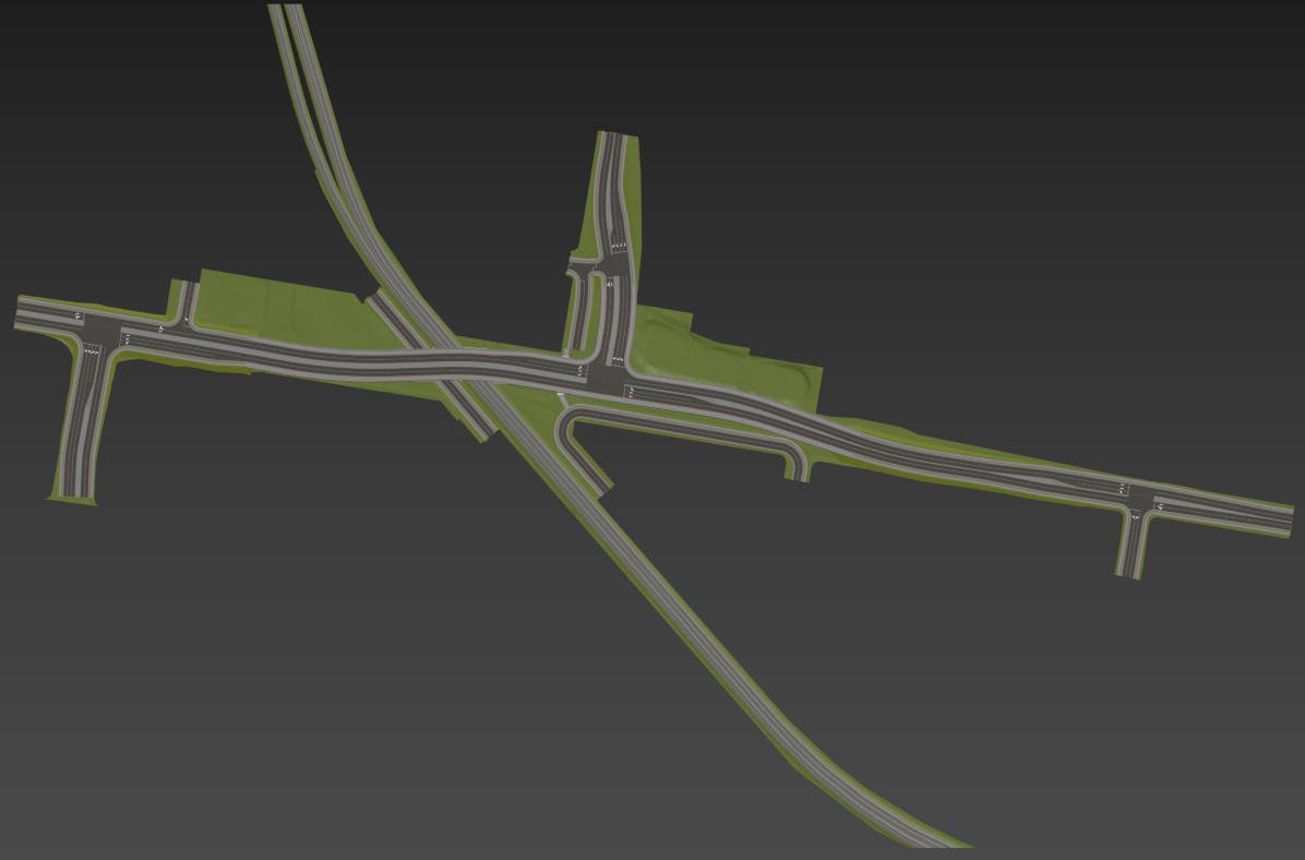
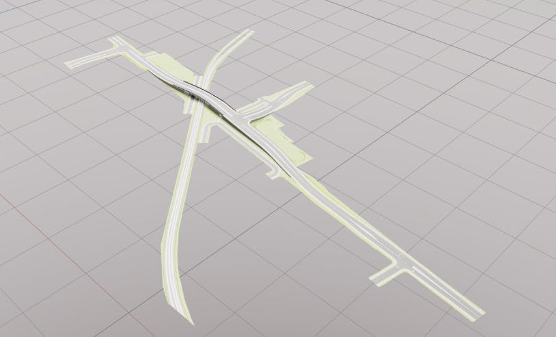
1Open your scene in 3ds Max. This tutorial assumes that you already have a 3ds Max scene geolocated to a UTM or similar projected coordinate system. If you are using the sample scene provided, it will look like the below image.
Because of 3ds Max single-precision coordinates, it is likely your scene has been offset closer to origin to maintain data accuracy. You will need to know the EPSG code of the original coordinate system for the source data, plus the value used to offset the data close to origin in order to follow this tutorial if using your own data.
2Select an object in the scene. Note the coordinates of these objects are relatively close to 0,0,0. This is because the design data originally from Autodesk Infraworks has been offset from its original projected coordinate system, many hundreds of thousands of meters away. We do this to ensure data accuracy, as 3ds Max reduces coordinate precision at far distances from the scene origin.
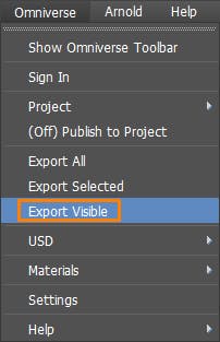
3Click on Omniverse > Export Visible to open the Create Content on Omniverse dialog.
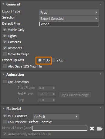
4Choose an export location and file name; then ensure Export Up Axis is set to Y Up. Click Export to publish your 3ds Max content to USD.
1Visit the epsg.io coordinate calculator in your browser.
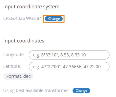
2Under Input coordinate system, click Change.
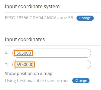
3Search for the EPSG code that represents the coordinate system for your project and select it. For this tutorial, our project data is projected in EPSG:28356.
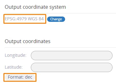
4Under Output coordinate system, ensure that EPSG:4979 WGS 84 is selected and that the format under Output coordinates is set to dec.
5Under Input coordinates, enter the EPSG:28356 location that corresponds to 0,0,0 in your 3ds Max scene. For our project, 0,0,0 corresponds to X: 503000 and Y: 6950000.
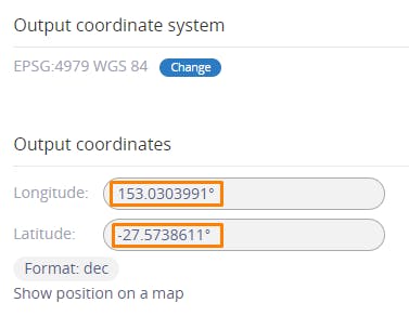
6Click the Transform button to convert the coordinates.
7The resulting latitude and longitude should be displayed under Output coordinates. Write these values down, as they will be used in the next step. You can also click Show position on a map to confirm the provided coordinates align with the correct location on Earth for your project.
1Open Omniverse USD Composer, ensuring the Omniverse Fabric Scene Delegate is enabled as per the quickstart tutorial.
2Click File > New to create a new empty scene. Remove the default ground surface.
3Click File > Add Payload, and select the USD file created during Step 1.
4Your 3ds Max content should now be loaded in the stage. If nothing is visible, press F to zoom extents.
5You might notice the content is quite small. This is because the 3ds Max source file uses meters, and Omniverse uses centimeters by default. Currently, the 3ds Max Omniverse connector does not automatically rescale your asset, so this needs to be done manually.
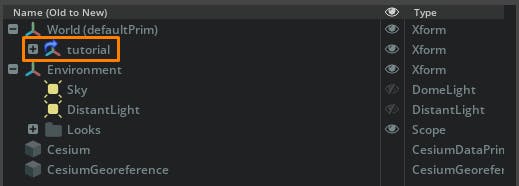
6In the Stage window, click on the payload that corresponds to your USD.
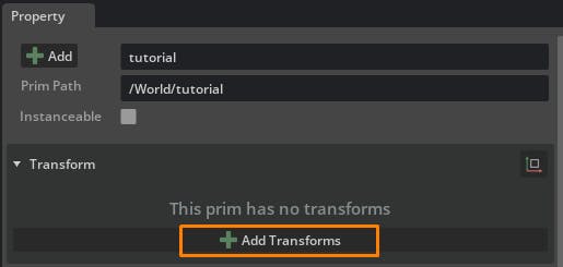
7Under the Property window, click the Add Transforms button.
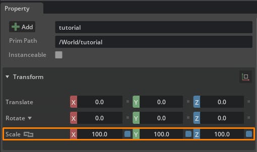
8In the Transform, enter a Scale value of 100, 100, 100. This will scale the 3ds Max content correctly in the Omniverse stage. Press F to zoom extents and see your resized content.
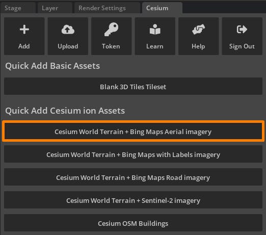
9From the Cesium window, add Cesium World Terrain + Bing Maps Aerial imagery to the stage.
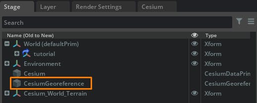
10From the stage, select the CesiumGeoreference prim to display its properties in the Property window.
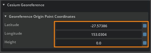
11In the Property window, enter the latitude and longitude obtained from EPSG.io. For now, enter the height value as 0.0. A more accurate height will be calculated in later steps.
12The design should now match accurately with Cesium World Terrain horizontally; however, it will still be positioned below the surface. This will be resolved in the next few steps.
13This 3ds Max design has height values defined based on mean sea level. Cesium World Terrain has its height values defined based on the WGS84 ellipsoid. To align the two as accurately as possible, the difference between mean sea level and ellipsoid height needs to be calculated. This difference can be used to offset Cesium World Terrain vertically.
14
Visit the UNAVCO Height Calculator in your browser.
15Under the coordinates box, enter the project’s latitude and longitude, followed by a height of 0.0, separated by commas. Click Submit.
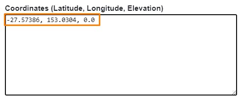
16Scroll down to find the results, and copy the value from the Geoid Height (m) column.

17Paste this value into the Height field of the CesiumGeoreference prim in Omniverse.
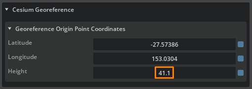
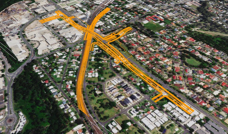
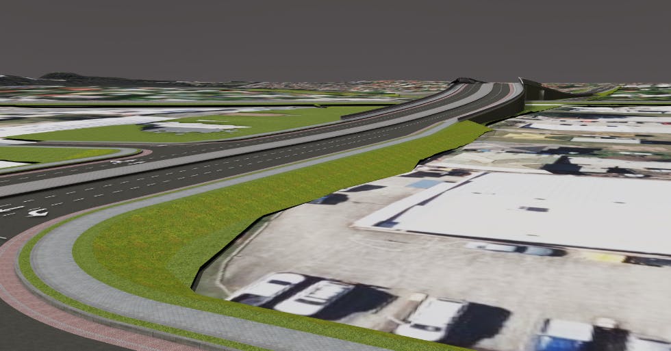
18Cesium World Terrain should lower and now accurately align with the terrain exported from 3ds Max.
Height datums used across projects will vary. Other methods may be required to accurately calculate the difference in height datum from your project data to Cesium World Terrain or other datasets you’re using.
Follow our Lighting the Stage and Capturing Images and Video tutorials to prepare your project and capture amazing visuals.